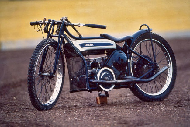
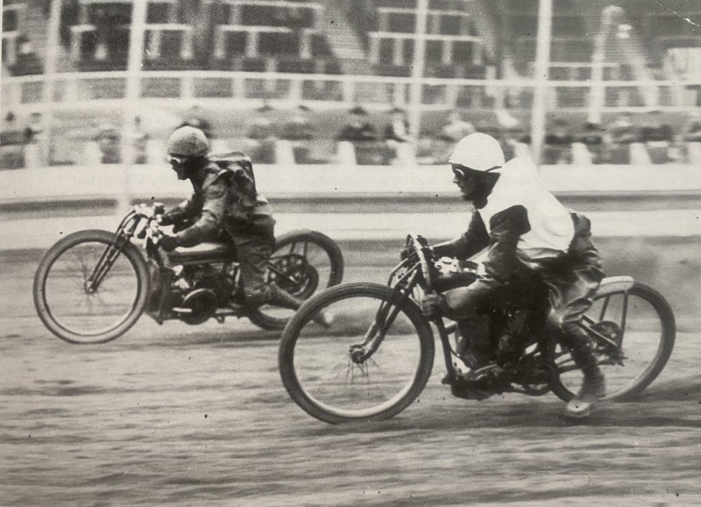
Background: Apparently, in 1923, sport of Speedway began in Maitland, Australia. However, other reports claim the sport began in South Africa in 1907.
American Board Track racing, held on oval tracks made from timber planks, some up to two miles in length, was certainly a precursor to Speedway. Board Track racing was dangerous and, in only a couple of decades numerous riders lost their lives. Due to the tracks requiring frequent expensive repairs, coupled with the fatalities and the Great Depression, the sport faded away.
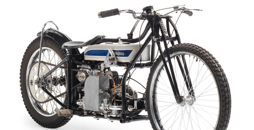
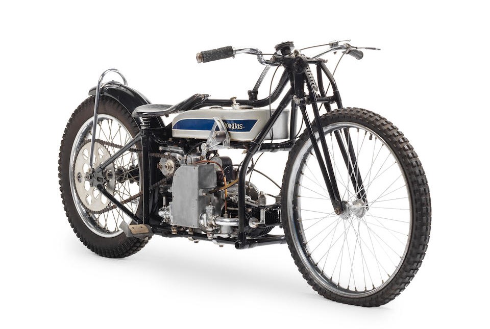
The first Speedway meeting in the UK was in Essex in February, 1928. The established brands involved in Speedway at that time included Harley Davidson, Indian, Excelsior. Peerless and Cleveland. Then, Douglas (as in motorcycles, sometimes known as Duggie), based in Bristol, UK decided to enter the sport with the DT5 in the late 1920s. Most of the DT5s were raced, crashed, fixed, raced, crashed, fixed ……roll on ninety-plus years, and there aren’t many examples of the DT5 remaining.
If you’re interested in finding out more about Douglas, the London Douglas Motor Cycle Club are friendly and a great source of information on Douglas bikes.
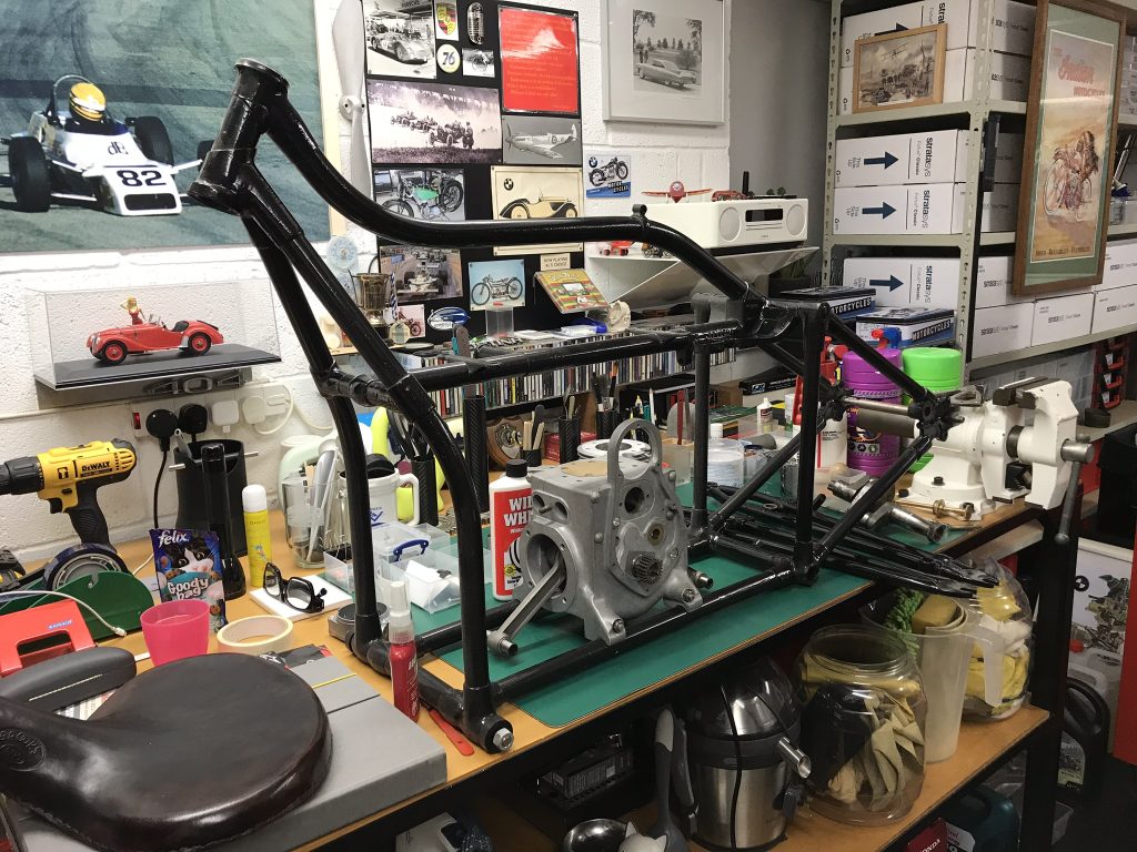
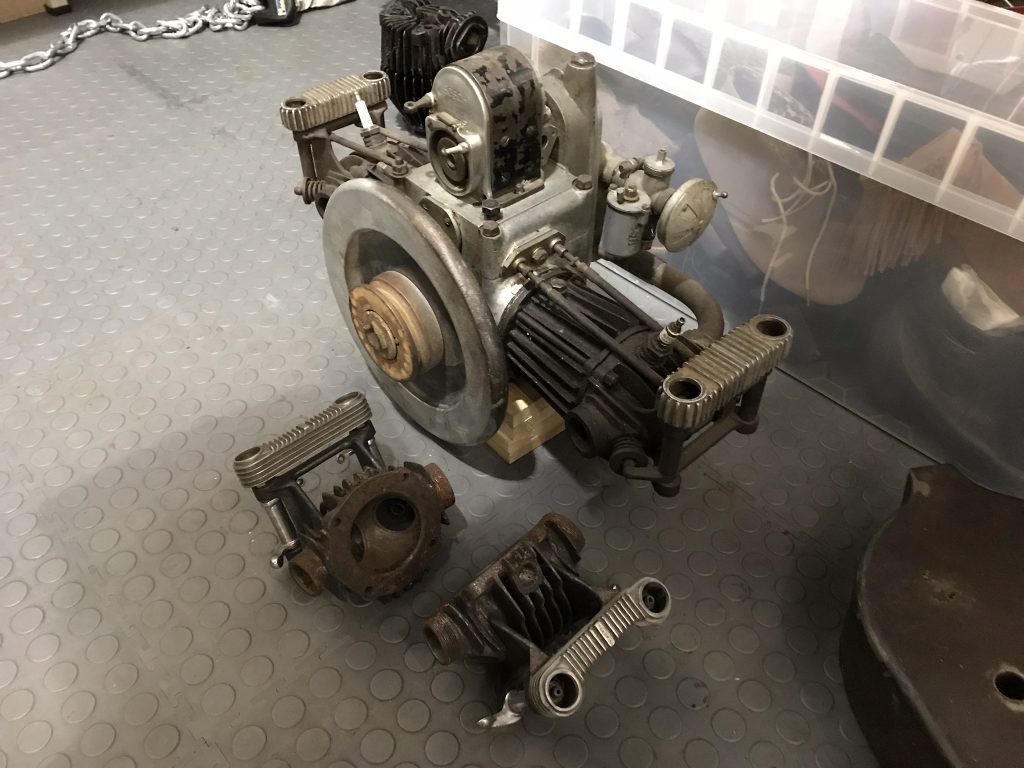
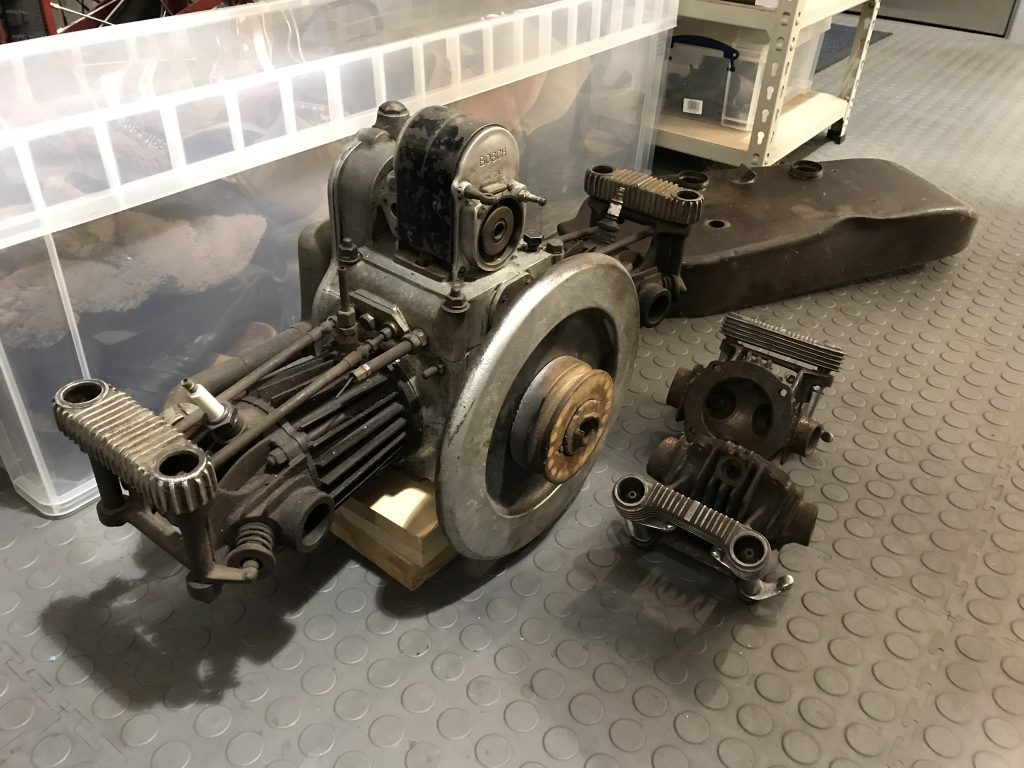
Engine: We have many parts to build a DT5, the most interesting probably being the motor. The motor was found on a farm in South Africa – perhaps some confirmation of the roots of dirt track racing in South Africa. The farmer had been using the Douglas twin to power a water pump. The farmer was offered, and duly accepted, a brand new Honda powered pump in exchange for the Douglas motor. The farmer must have struggled to believe his luck.
If you look closely at the pictures of the motor you can see a v-belt pully turned from wood still on the crankshaft. This pulley was used to drive the water pump via a v-belt.
Douglas used a flat twin configuration but mounted it transversely in the frame. One of the cylinders pointed forwards and the opposite cylinder rearwards. Apparently the rear cylinder ran hotter than the front due to less airflow and cooling.
We have been lucky enough to acquire many, but not all, the parts required to build a DT5. The main parts missing are frame and forks, so not insignificant.
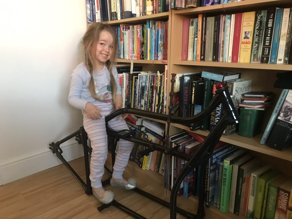
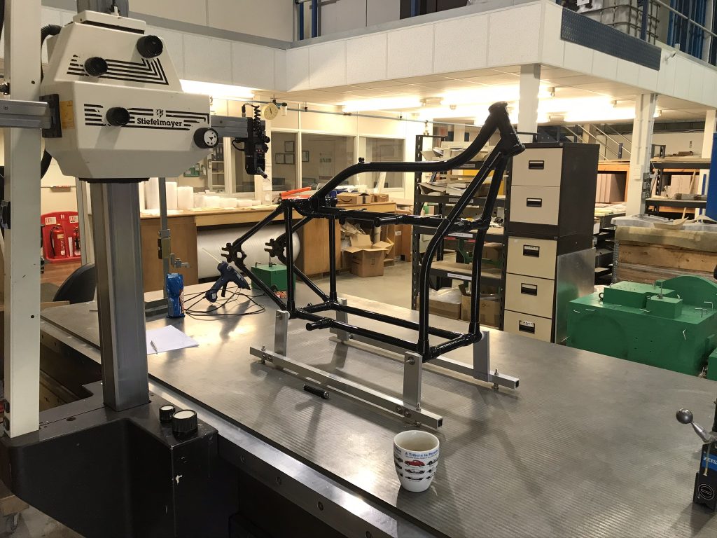
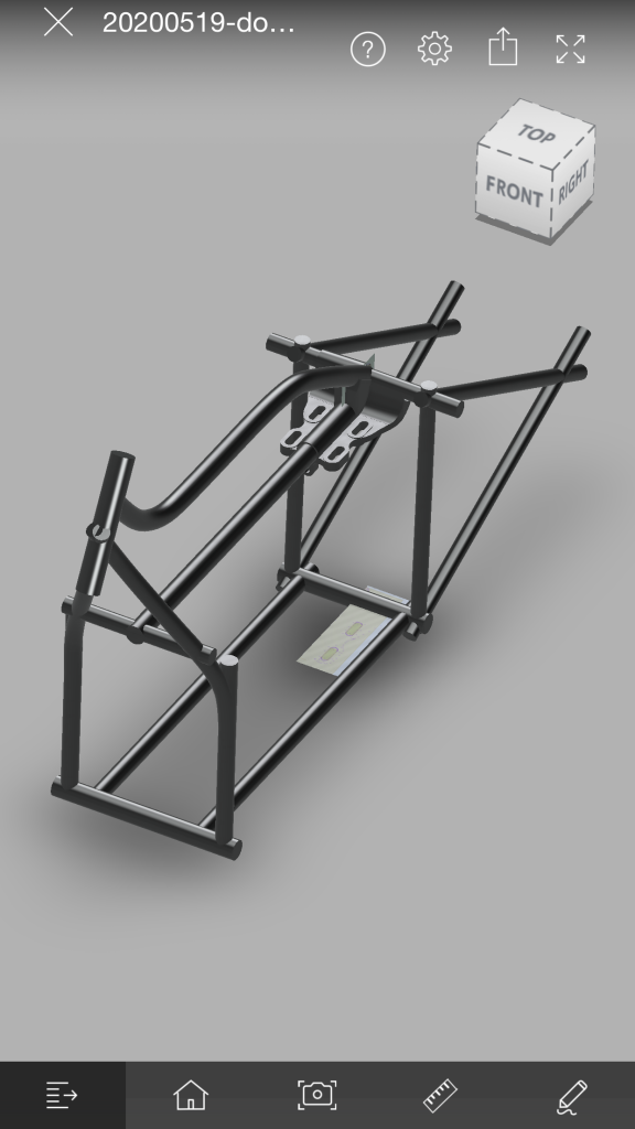
Reverse Engineering the Frame: Measurement: We managed to source a genuine DT5 frame and forks on loan from a friend – they spent 3 decades in Formula 1 and are meticulous about their builds with attention to detail second to none – so no pressure. This was a generous offer due to the scarcity and value of these parts. We were very grateful and looked after the parts beautifully. These were used to create a digital twin of the original parts.
The original Douglas frame design used tubes joined by lugs, somewhat similar to many bicycle frames. When made, the tubes were positioned in the lugs using a jig to get the correct orientation. Douglas then drilled through the lugs and tubes and fixed them in place using spring pins. The joints were then brazed and the spring pins remain in place.
The coordinate measurement machine (CMM) activity was done by Kevin at Kestrel Technologies. Kestrel is a family business run by father and son, Kevin & Ben. They have a very knowledgeable and professional team based in the South East of England. They do lots in the composites industry including pattern making, tooling board as well as exotic metals and are very versatile. Kestrel have helped with other projects including machining of moulds for an aluminium casting project too – more on that in a separate post.
A good proportion of CMM operation is in the skill of the operator – the CMM used for this was a large scale, manually operated model. A short video of the CMM being calibrated using the spherical calibration tool has been included.
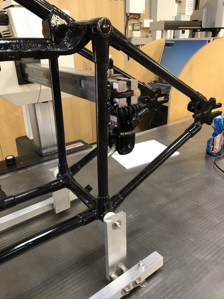
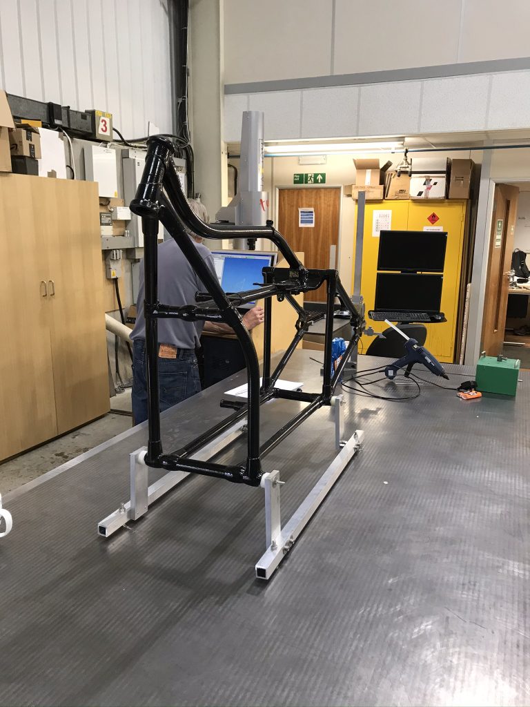
The Douglas frame was mounted on an aluminium sub-frame to raise the lower rails from the CMM bed – otherwise the CMM probe wouldn’t have easy access to all frame rails and surfaces. The support frame was then bonded to the bed of the CMM to prevent movement whilst measurements were taken.
At each end of the frame rails numerous points were taken around the outer circumference. A similar procedure was used for the curved frame rails but additional, intermediate measurements were taken – enough to be able to accurately plot the frame rail path.
Each time the CMM probe is touched onto the surface of the frame a ‘point’ is recorded. All measurements (CMM points) were recorded in a file by the CMM. The format of this file is basic and is essentially a list of all the point measurements taken in 3D space from a defined origin. This file is referred to as a ‘point cloud’. See the illustration below and example corresponding point cloud file entries for each point (A, B, C and D). The intersection of the three axis is the ‘defined origin’ so all point measurements are relative to this.
Point A: x = 5, y = 1, z = 2.
Point B: x = 5, y = 4, z = 2.
Point C: x = 3, y = 1, z = 2.
Point D: x = 3, y = 4, z = 2.
In short, the frame tube axis lines were modelled from the point cloud data. The point cloud data showed the outer diameter of the frame tubes at key locations – like joints.
Although not a current priority, the plan is to use the CAD data to create a new frame. Perhaps a variation on the original theme that exploits the motor and other parts available.
There is no desire to complete this project and try to claim the reverse engineered frame as original. If an original frame became available then that might be an option and an excellent opportunity but the current assumption is that this is very unlikely. Also, if one does turn up it is likely to be expensive.
Reverse Engineering the Frame: Digital Twin Creation: The raw CMM point cloud file was opened in CAD – this was Autodesk Inventor / Fusion 360 at the time but we’ve been migrating to Solidworks recently. Solidworks is a significant uplift in cost over what we’re used to but we’ve had excellent support from Visiativ UK – more to follow on that in a separate post.
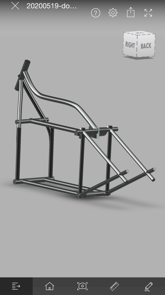
The DT5 frame has a ‘goose neck’ shape past the petrol and oil tank to the headstock tube. Other than these tubes, the majority of the DT5 frame is straight lines between points therefore reasonably straightforward to model accurately.
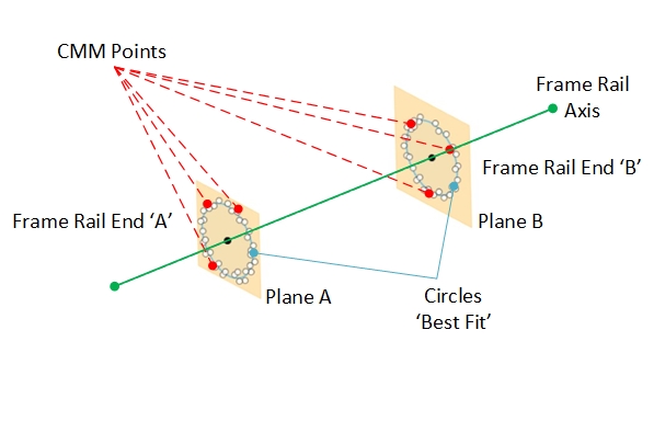
An illustration has been included to show how the CMM data was used to create the Douglas frame digital twin. A similar procedure was repeated for all of the frame rails.
The raw CMM data file was loaded into CAD. The CMM points are represented by the white dots in the diagram.
A ‘set’ of CMM points were taken at both the ‘A’ and ‘B’ ends of each frame rail. A plane was created within CAD through each set of CMM Points – Plane A and Plane B are shown in the diagram by the beige rectangles.
The CMM points were used to create ‘best fit’ circles (shown in blue on the diagram) on both Plane A and Plane B. The CMM points recorded imperfections and / or damage in the frame tubes and differences in the thickness of paint, etc hence ‘best fit’ circles.
The accuracy of this method, although not perfect, was acceptable. As mentioned, the donor frame wasn’t ours so we couldn’t strip the paint to gain access to bare metal. Also, we’re not sure how accurately Douglas built these frames in the first place as there were measurable differences between the same features side to side.
If you imagine the frame in two halves as you sit on the bike, most of the measured differences between each half were removed by taking the average of the differences. These average dimensions were then used to model one half of the frame. Once complete, the half frame could then be mirrored in CAD producing a frame that matched the original intent but without side to side differences. Some of the differences could have been from crashes or repairs made to the frame over it’s ninety plus year life.
The circle centre points for the best fit circles at either end of the frame rail were used to create frame rail centre lines / axis (shown in green in the diagram).
A centre line / axis ‘skeleton’ of the entire Douglas frame was created using the same procedure.
Frame rail sections, lug details, front and rear axel dropouts and other frame features were added based on the frame rail centre line / axis skeleton plus additional measurements – CMM and manual.
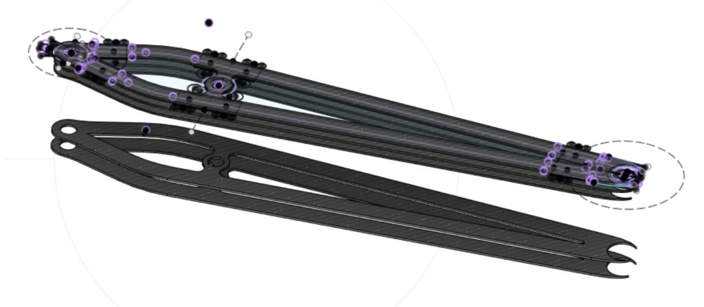
The DT5 uses girder forks. These were reverse engineered using similar methods to the frame apart from not requiring the use of the CMM. Due to the fork leg being flatter it was possible to quite accurately model these using manual measurement methods. A couple of images of these parts are given below. The forks may be the focus of a future post.
