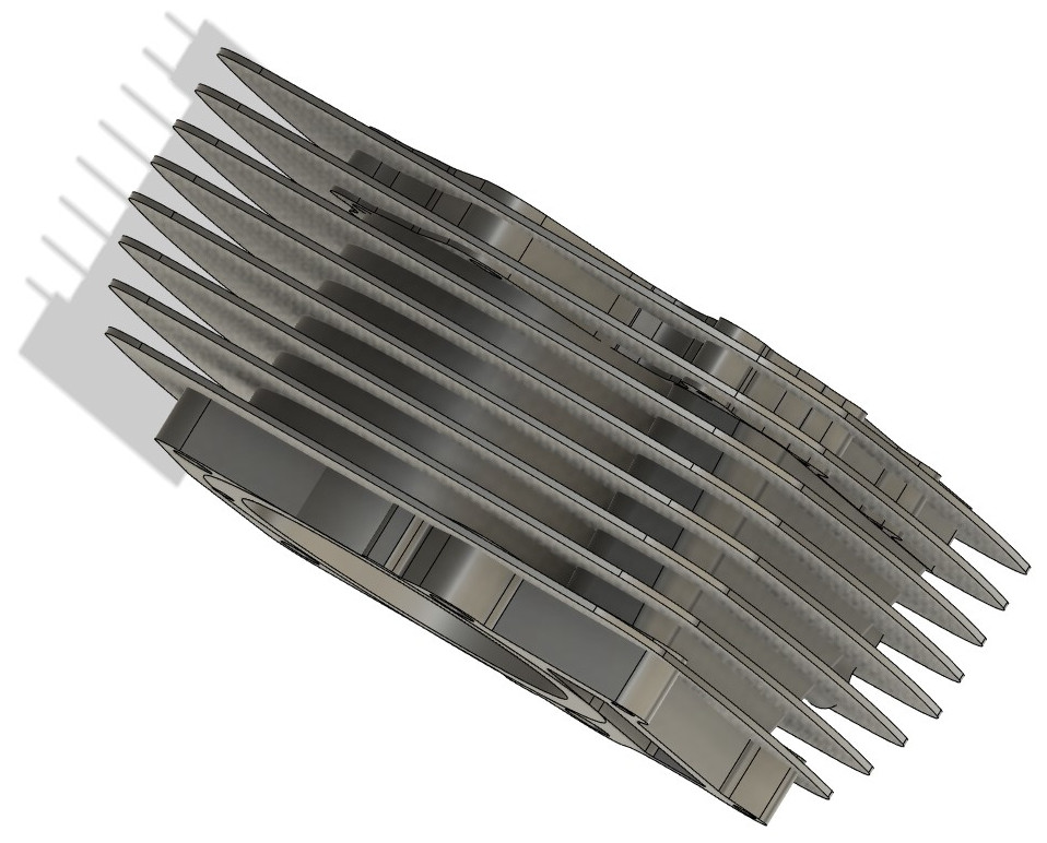
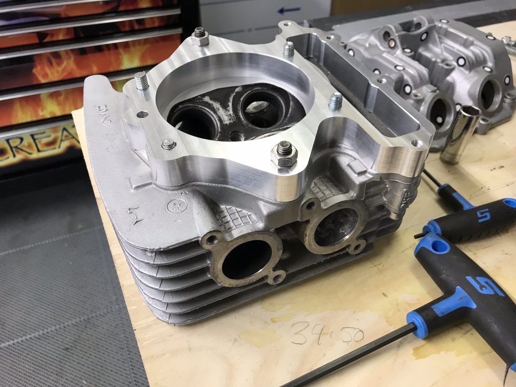
Background: This project started out as part of a Yamaha XT 600 – 660 ‘Frankenstein’ motored (bottom end from an XT660 but top end from an XT600 as we wanted to keep the air cooled look) flat track framer bike. The original intention was to cast a new cylinder with modified, more symmetrical, fins that had a more uniform appearance regardless of the angle the motor was viewed from.
This quickly scope-crept, to be a remodelled cylinder head and cam-box. There were numerous reasons for doing this including redesigning the cylinder head and cam-box to use a more serviceable cam bearing setup (e.g. plain bearing shells). The standard cams run directly in the aluminium bearing journals so any oil supply issues often result in a ruined camshaft, head and cam-box.
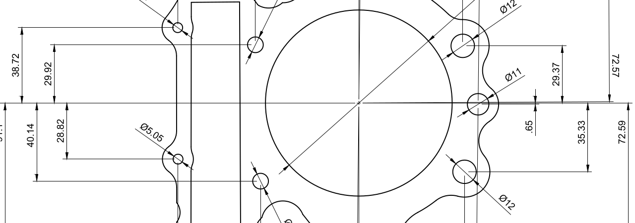
Reverse Engineering: CAD Creation: Time is precious and in short supply. Due to other priorities, we’ve only got as far as creating a digital twin of the parts. This process began by getting the standard parts into CAD. We used a combination of 3D scanning and measurement. At the time, 3D scanning wasn’t quite accurate enough – at least the technology we used. For example, the scan data couldn’t have been used on its own to model, dimension critical, features such as the cylinder bore axis, bolt hole centres, oilway channels, etc.
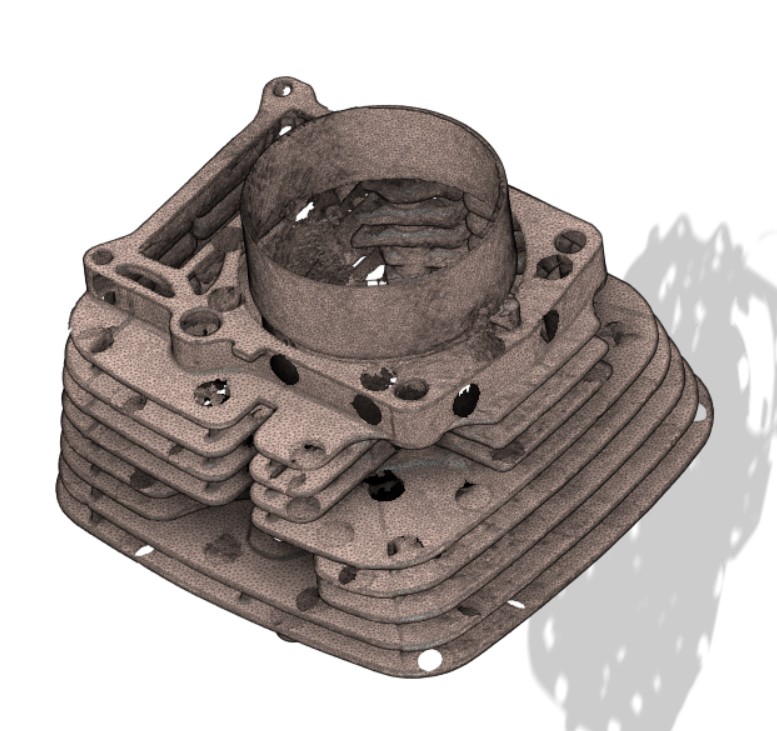
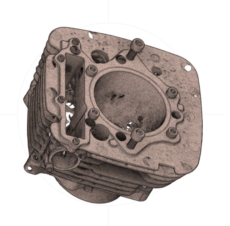
However, it was very useful to have the 3D scanned data to hand – much easier than carrying the top half of the motor around. It proved useful to have both the 3D scanned image on the screen at the same time as the CAD.
The 3D scanner used positioning dots (black circle with white centre) stuck to the part surfaces to help orientate the scanned data.
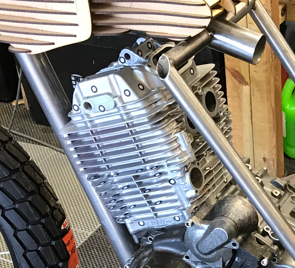
The 3D scanned data could be opened and manipulated in CAD. Although we didn’t use this data to determine dimension critical features it was used it to obtain the shape and profile of the features like the cylinder cooling fins. The 3D scanned data was invaluable for this type of activity. 3D scanning technology has moved on significantly in the last few years both in terms of accuracy but also the affordability of decent quality systems.
This data was then used to create surfaces in CAD. These surfaces were needed to correctly orient the various components and ancillary parts. Although the plan was to modify the appearance of the cylinder, certain features had to be carried over into the new design. Examples of this included the cylinder base to crankcase surface, bolt hole centres, cylinder bore axis, chain tensioner mating surface, etc.
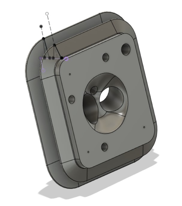
Another use case for the 3D scanned data was creating the combustion chamber. This would have been difficult to model if it weren’t for the 3D scan. The complex curved surfaces of the combustion chamber were modelled using multiple solid bodies (e.g. rectangular box shapes with filleted edges, spheres, etc). These solid bodies were manipulated to mimic the actual surfaces as per the 3D scans. The solid bodies were then used to remove material (e.g. Combine / Subtract in Solidworks or Combine / Cut in Fusion 360) from the cylinder head leaving an accurate copy of the original. No doubt there’s easier or more automated ways of achieving this which we’re currently experimenting with.
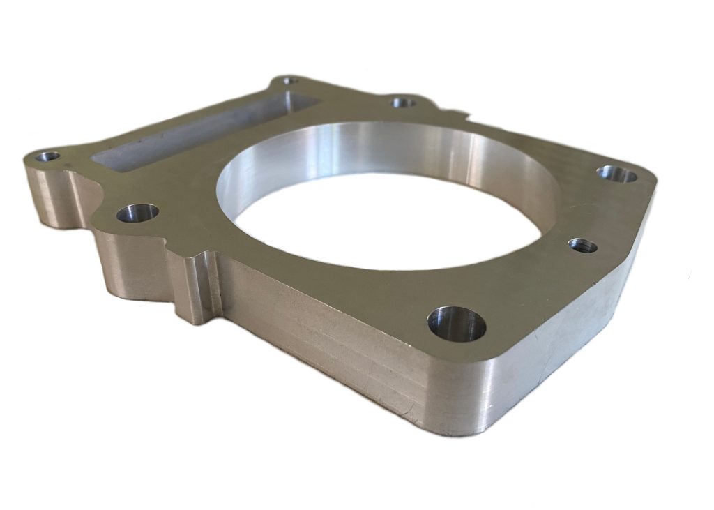
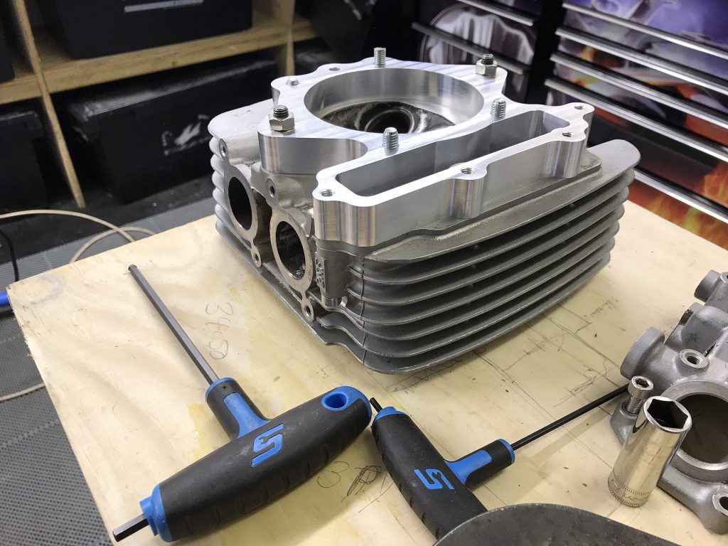
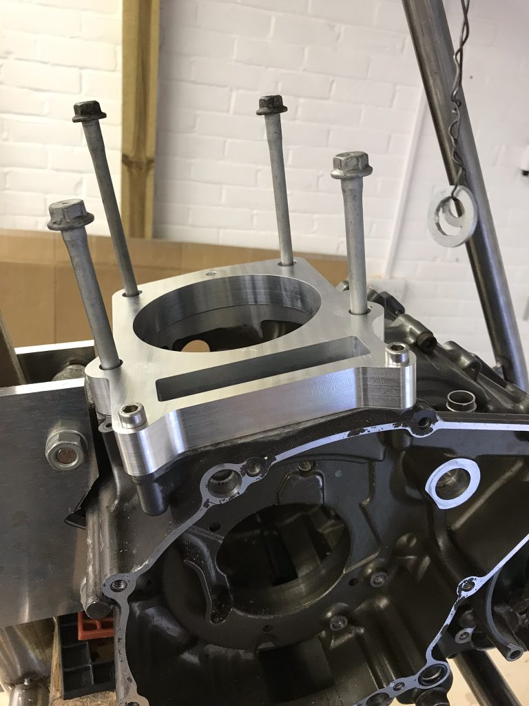
Reverse Engineering: Design Data Validation: From the detail determined in the previous steps, aluminium fitment gauges (or plates) were manufactured by Kestrel Technologies. CAD data was used to create the CNC toolpaths with the sole aim of confirming the accuracy of key dimensions and features. Checking fitment at this stage meant we didn’t have to spend the time and money to have sand casting moulds, castings, final machining, etc only to discover the raw data was wrong.
Two gauges were made. One for the cylinder base to main case interface and another for the cylinder top to cylinder head. Standard dowel pins were used to ensure the gauges located in the correct position. Other features, such as bolt holes, were machined to provide clearance so couldn’t have been used for accurate positioning. It was important to ensure, with the dowel pins in place, that all other features were correct and that bolts could be located, and tightened, without binding.
Sand Casting Thin Components: Creating a casting of a component like a cylinder is challenging and requires specialist knowledge of mould design, molten metal flow, contraction, metallurgy, material properties, etc. The pattern (mould) maker and foundry need to be closely coupled and have an in-depth understanding of each other’s roles, requirements, limitations and challenges.
This is true for most metal casting processes, but especially sand casting. With sand casting, the molten metal is fed under atmospheric pressure. The sand moulds aren’t heated. Therefore, the molten metal is cooling as it flows through the mould. If the pattern maker hasn’t considered this during the design then the molten metal can cool and solidify before reaching all mould extremities and cavities leaving voids, porosity, poor surface finish, etc in the final casting – these castings would typically then be scrap.
This is true for a shape like a cylinder, especially the cooling fin details that are relatively long compared with their thickness – they also have a high surface area to volume ratio (which is the point of a cooling fin). These characteristics make casting in sand of a cylinder more challenging than, say, a less complex, thicker or more blocky shape.
In contrast, high pressure die casting, the molten metal is fed into the mould under high pressure. Die cast moulds are metal, are typically very expensive and can be used for high production runs. Die cast moulds can be heated during the casting process. These methods keep the molten metal more fluid which reduces cycle time, helps ensure the entire mould is completely filled thus minimising voids or cavities in the finished component. Due to the high cost and significant investment in machinery, die cast methods aren’t typically used for low run casting projects.
