There are a few considerations required in relation to the design and manufacture of a bespoke framed flat track framer bike – actually for any design project. Writing this type of information down is a useful step and can promote valuable thinking time and provide crucial input early in the design process. Writing these down can help focus later in a project and can (should), of course, be reviewed as part of the ongoing design process.
Firstly some constraints – not an exhaustive list:
- Finances are limited.
- Manufacturing will likely need to be subtractive (machined). Although welding is possible we don’t have the specialist skills or equipment. Specialists in this area are typically very busy, especially the talented ones. Specialists can also be expensive, especially the talented ones – understandably, they need to pay their bills too.
- The frame design can be optimised for strength, stiffness, weight, cost, etc. Our design will prioritise weight reduction (as light as possible) and strength (strong enough not to break but no stronger with allowance for a safety factor).
- Stiffness is slightly more tricky because stiffness can impact the handling of the bike. As a good example, but probably a gross generalisation, stiffer chassis can offer less grip on more bumpy, slicker track surfaces. Flat Track bikes often race on very mixed surfaces, some are more bumpy, some begin slick but then gain grip during an event plus many more variations. Flat Track bikes also rely on quite varied handling characteristics such as being able to slide controllably in a corner but then able to generate drive out of a corner and down the straights.
Then the opportunities – not an exhaustive list:
- Minimise our dependencies on suppliers (e.g. frame builders) and be more in control of our own destiny.
- Learn by doing.
- Being able to adapt the design as required. This is more tricky when you commission someone else to do something for you. Talented folks in the fabrication space are often very busy and can be picky about the work they take on – they can also be a little prickly if their dumbass customer keeps changing their mind.
Regards the design of the chassis itself, there are a few options:
1) Don’t do it. Go and do something else instead.

2) Enrol the services of someone clever who knows typical load case data – very unlikely. Probably expensive and doesn’t demonstrate our goal to be less dependent on others.

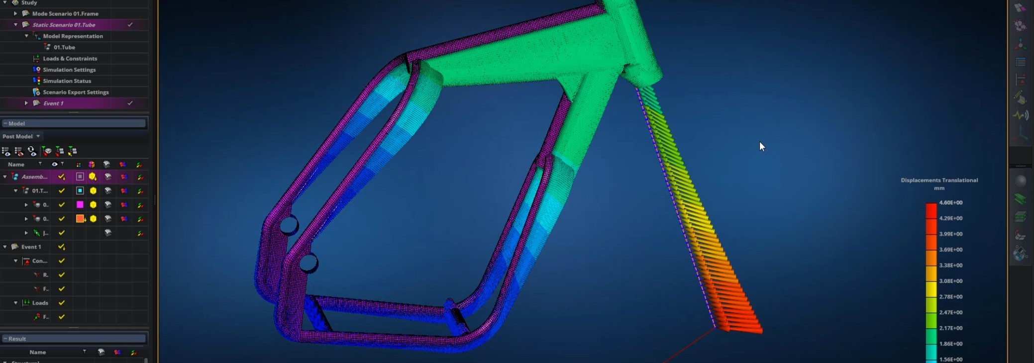
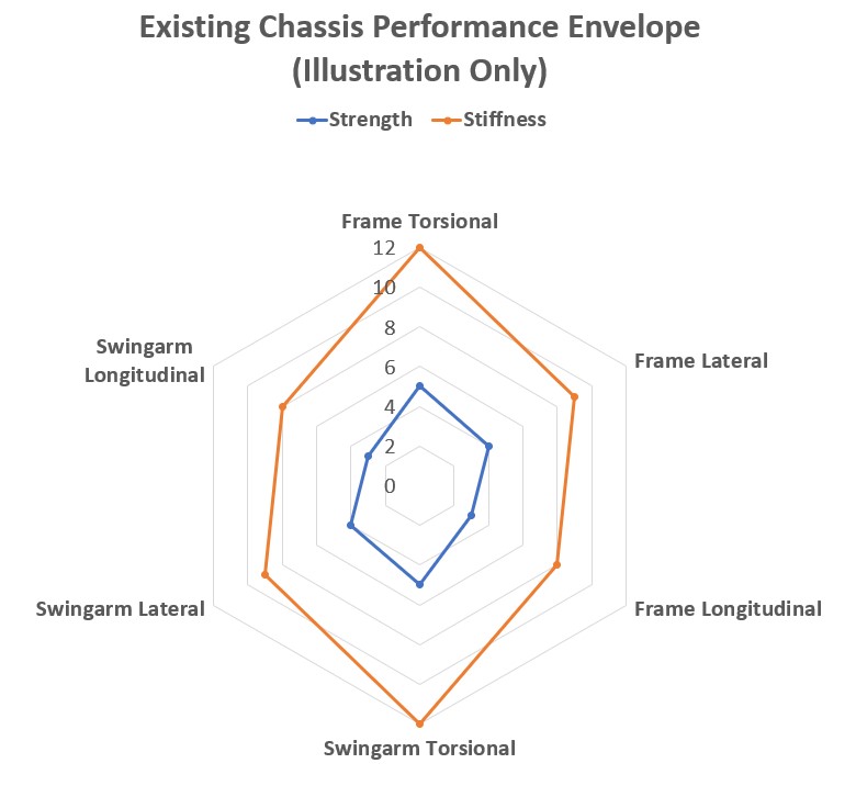
3) Use an existing design that we know works – as in it doesn’t fail when subjected to flat track racing loads. We can model an existing frame in CAD and, provided we know the material properties, tube dimensions, etc, this information can be used to determine a strength and stiffness ‘envelope’ within which we can design the new frame. This is probably the most cost effective method however the new design couldn’t be optimised – beyond the existing modelled frame – for weight, strength, etc.
4) Guess. Perhaps an educated guess of the load case data. Probably the easiest option (apart from option 1) however I’d likely be consumed by the doubts in my head. This approach minimises the opportunity to optimise the design for minimal weight if the load cases aren’t representative of the real world. We could exceed the elastic limits of the material, leading ultimately to failure.

5) Measure loads whilst subjecting the chassis to actual use. This method overcomes most of the issues with the other methods.

Option 5 above is the favourite however there are challenges that need to be overcome. These include, but are not limited to:
- What loads to measure?
- How to measure the loads?
- Where to measure loads?
- How to collect the measurements?
- How to make sure measurements (aka channels) are synchronised relative to each other.
- How to interpret measurements?
- How to use measurements in our chosen simulation software?
- Ahh yes, and a bike (aka strain gauge ‘mule’) to enable all the above.
Wolf Star Technologies have developed software utilities, the flagship one being True Load (TL). TL serves many purposes including solutions to the challenges described above, crucially the following:
- Use of existing CAD data, FEA and simulation software tools to determine the correct placement of load measurement devices (e.g. strain gauges).
- Create multi-channel load cells from appropriately positioned strain gauges on a structure.
- Calculation of load Vs time histories that accurately (typically within 2%) match the measured strain.
Once TL has compiled a reference data set, this information can be exported as input load case data to your chosen CAD /FEA / simulator software tools. Safety factors and other design considerations can of course be applied. The design can be modified and optimised as often as required and the load case information re-applied. The combination of good quality CAD models, TL, strain gauges that measure actual operating loads results in a very powerful and effective simulation tool.
We plan to use TL in association with Wolf Star Technologies and share our progress on this blog.


